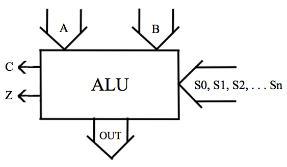
A group of input signals are represented by the arrow marked A, and the same number of signals is represented by the B arrow. This number of signals might be 8, 16, 32, 64, 128 or a greater number. The number is usually a power of 2. These are data inputs which may be used by the ALU as two numbers to be added together or used in any of various arithmetic or logical operations requiring one or two inputs and producing the ALU output shown as OUT in the figure. The number of bits in the output is the same as the number that is in each of the inputs. The ALU is typically capable of adding and capable of logical operations such as AND, OR, XOR, and NOT.
The logical operations presented in chapter 1 produce a single output from one or two inputs. The logical operations performed by an ALU operate on one or both of its multi-bit input numbers and produce an output. This is done bitwise. For a logical operation, the first bit from each of the A and B inputs produces the first bit of the output number, and the ith bit of each of the A and B inputs produces the ith bit of the output number.
Something must select the operation that is to be done by the ALU at any given time. This is done by the select inputs, which are named in the figure as S0, S1, etc. They are often between 4 and 6 in number.
There are individual outputs which characterize the last calculation done by this particular ALU. The outputs shown in the figure indicate a carry out, C, and a zero result, Z.
Z is in its defined active state (logic high or logic low) whenever the result of the most recent calculation made by the ALU is zero. If Z is defined as an active high output, Z is at logic high (1) whenever the most recent calculation made by the ALU is zero. If the defined active state is logic low (0), Z is at logic low (0) whenever the most recent calculation made by the ALU is zero.
If C is a logic low carry output, it is at logic low whenever the most recent calculation produces a carry out.
There are other possible outputs of the ALU that can characterize the last calculation executed. They each have uses. For instance, a programmer wishing to add two 16 bit numbers on computer having an 8 bit microprocessor can use the carry bit to add to the second pair of 8 bit numbers.
The ALU can be described with a truth table. Here is a purely hypothetical one:
	S0 S1 S2 S3 	Output
	----------------------
	0  0  0  0 	A + B
	0  0  0  1 	A AND B
	0  0  1  0 	A OR B
	0  0  1  1 	A XOR B
	0  1  0  0 	A NOT B
	.           	.
	.           	.
	.           	.
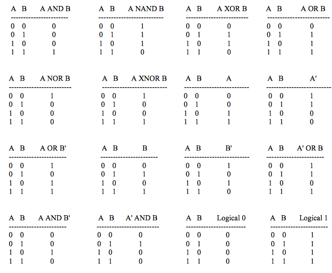
It is common for microprocessors to have an ALU that is capable of all 16 possible logical operations. Here are those operations:
Contact
https://www.futurebeacon.com/jamesadrian.htm